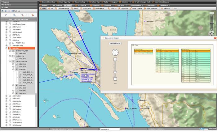
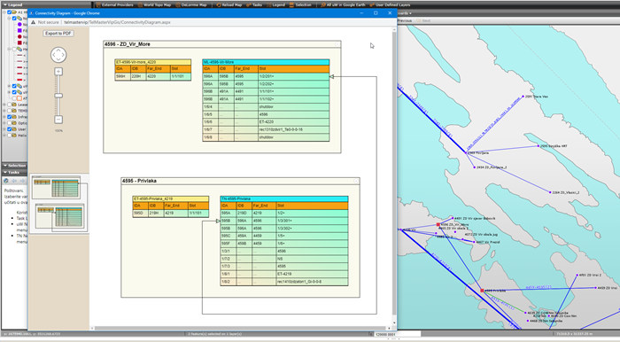
•Connectivity diagram for multiple interactively selected Nodes.
oMap context menu - Connectivity diagram.
▪Connectivity diagram is created on-the-fly to provide insight into logical uW network structure.
▪Traffic Node (TN) transmission equipment is visualized with dynamically created tables having all TN WAN and LAN connections.
•Collocated TN's are grouped together in the Site location box.
•Diagram shows WAN interface and LAN access ports for each TN.
oConnectivity diagram opens in Pop-up window.
▪Have integrated overview window for easier navigation of large diagrams..
▪Diagram Pan is enabled with Alt + left mouse button or mouse middle button.
▪Diagram have export to PDF function.

Figure 13: TN equipment with WAN and LAN interfaces in selected node.

Figure 14: TN Connectivity diagram for two selected Nodes.