Please enable JavaScript to view this site.


Logical transmission network layout is automatically created for network elements selected on TelMasterGIS and is called Connectivity diagram.

oConnectivity diagram represent interface between physical and logical network structure.
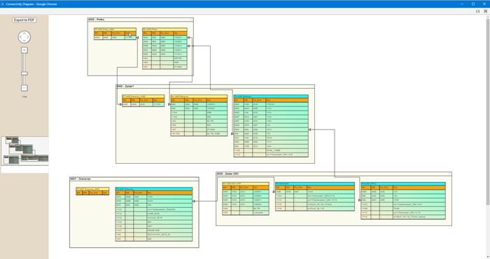
 

Figure 30:  Connectivity diagram for logical network structure.

Figure 30:  Connectivity diagram for logical network structure.


Keyboard Navigation

F7 for caret browsing
Hold ALT and press letter

This Info: ALT+q
Page Header: ALT+h
Topic Header: ALT+t
Topic Body: ALT+b
Contents: ALT+c
Search: ALT+s
Exit Menu/Up: ESC